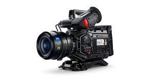
The Blackmagic Design Spares - Camera URSA Mini Pro 12K - PCB Rear SDI is the dedicated interface board responsible for the high-bandwidth video output and input located at the back of the URSA Mini Pro 12K. Because this camera is designed for 12K workflows, the SDI architecture is incredibly robust, handling 12G-SDI signals that can carry 4K and 8K 60fps monitoring feeds with ease.
Functional Roles
This PCB acts as the physical and electrical gatekeeper for the camera's external video signals.
-
12G-SDI Main Output: Provides the primary high-bandwidth feed to external recorders, high-end monitors, or wireless video transmitters.
-
12G-SDI Return Input: Allows for program return feeds, which is essential when using the 12K in a studio or live broadcast environment for Tally and Talkback.
-
Reference/Timecode Processing: Typically houses the BNC connections for Genlock (Ref In) and Timecode (In/Out), ensuring the camera stays in perfect sync with the rest of the production.
-
Signal Re-clocking: Features integrated chips that "clean up" the digital signal before it leaves the camera, allowing for longer cable runs without signal degradation.
Why You Might Need a Replacement
The rear BNC connectors are among the most common failure points on any professional camera due to the physical leverage exerted by heavy SDI cables.
-
Snapped BNC Connectors: If a cable is tripped over or the camera is dropped on its rear, the BNC connectors can be sheared off the board or have their internal pins bent.
-
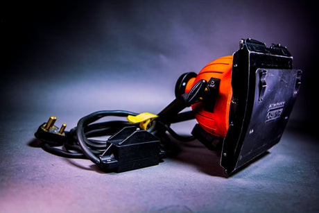
SDI "Blowout": A common industry issue caused by "hot-plugging" SDI cables while using faulty or cheap D-Tap power cables. This causes an electrical surge that fries the SDI driver chips on this specific PCB.
-
Intermittent Sync: If the camera refuses to lock to external Timecode or Genlock despite verified cables, the processing logic on this board may be faulty.
-
Physical Port Wear: After thousands of connections, the BNC locking "teeth" can wear down, leading to a loose connection that causes signal "flicker."
Key Features
-
12G-SDI Rated: Engineered with the specific impedance and shielding required for 12Gb/s data rates; lower-spec boards from the original URSA Mini will not work.
-
Modular Design: Because this is a separate PCB, you can replace the damaged ports without needing to buy a new (and far more expensive) Main Board.
-
Genuine OEM Fit: Ensures the BNC connectors line up perfectly with the pre-cut holes in the URSA 12K’s magnesium chassis.
Technical Installation Note
Replacing the Rear SDI PCB is a mid-level repair, but it requires careful handling of the camera’s internal interconnects.
-
Ribbon Cable Management: The board connects to the Main PCB via high-speed ribbon cables. These must be seated perfectly square. If they are slightly crooked, you may get "sparkles" in your video output or no signal at all.
-
BNC Nut Tension: When installing the board, ensure the nuts securing the BNC connectors to the chassis are tight but not over-torqued. Over-tightening can crack the PCB or strip the threads.
-
Isolation Check: Ensure the clear plastic insulation sheets (if present in your revision) are re-installed between the PCB and the camera body to prevent short circuits.
-
Testing "Return": After installation, test both the Out and the In ports. Sometimes a board will successfully output video but fail to receive a Return/Tally signal if the input processing chip isn't seated correctly.
Pro Tip: To avoid needing this spare in the future, always use BNC "pigtails" or SDI strain-relief brackets. It is much cheaper to replace a 6-inch jumper cable than the internal SDI PCB!
Is your camera failing to output any signal at all, or are you seeing intermittent "flickering" that suggests a physical port issue?